Get a quote for this product
Quantity, destination country and your specification if you have one. A technical answer comes back the same day; pricing is prepared by a person, never auto-generated.
Request a QuoteTell us quantity, country and mounting type — a technical answer comes back the same day.
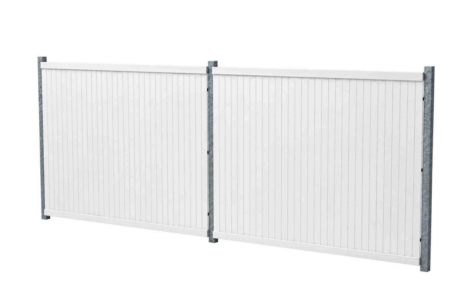
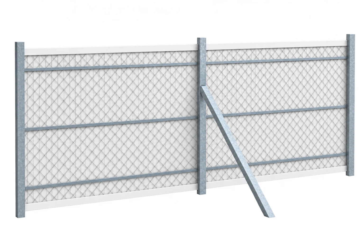
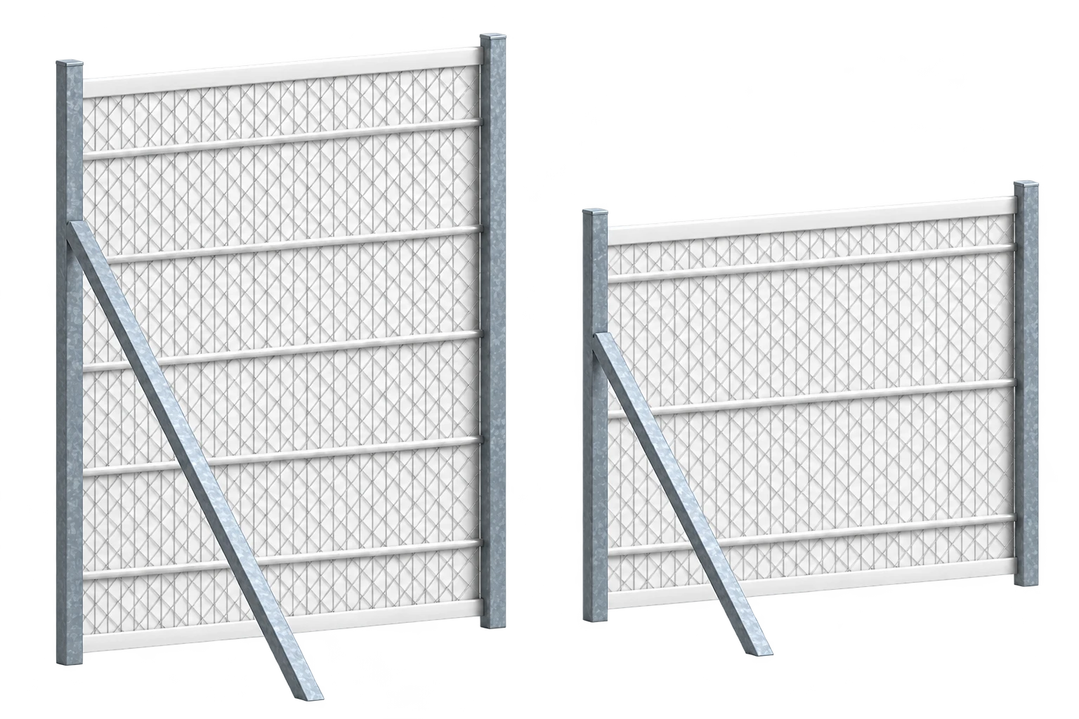
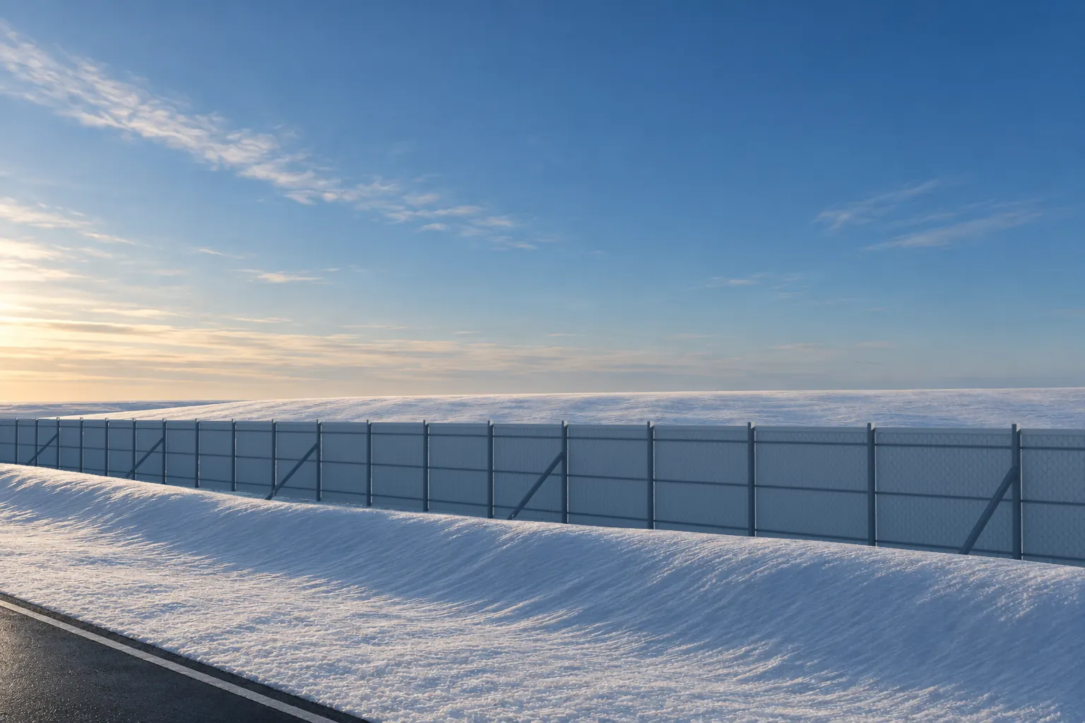
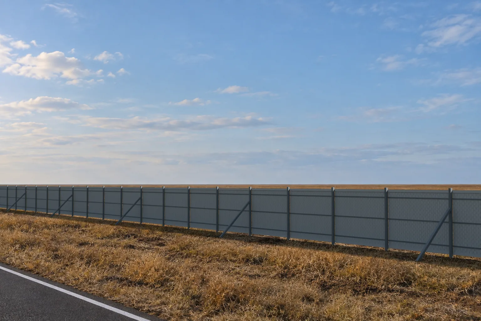
The GRP snow fence is installed along the roadside to help reduce wind-driven snow reaching the road. GRP louvre panels are placed between galvanised steel posts. Two standard heights are available (1.50 and 2.30 m); other heights and lengths are made to order. The −30 °C impact test and galvanising values in the manufacturer’s datasheet are requirements; product/batch test and coating reports are verified for the quotation scope.
| Height | 1.50 m · 2.30 m |
|---|---|
| Post spacing | 2.00 m |
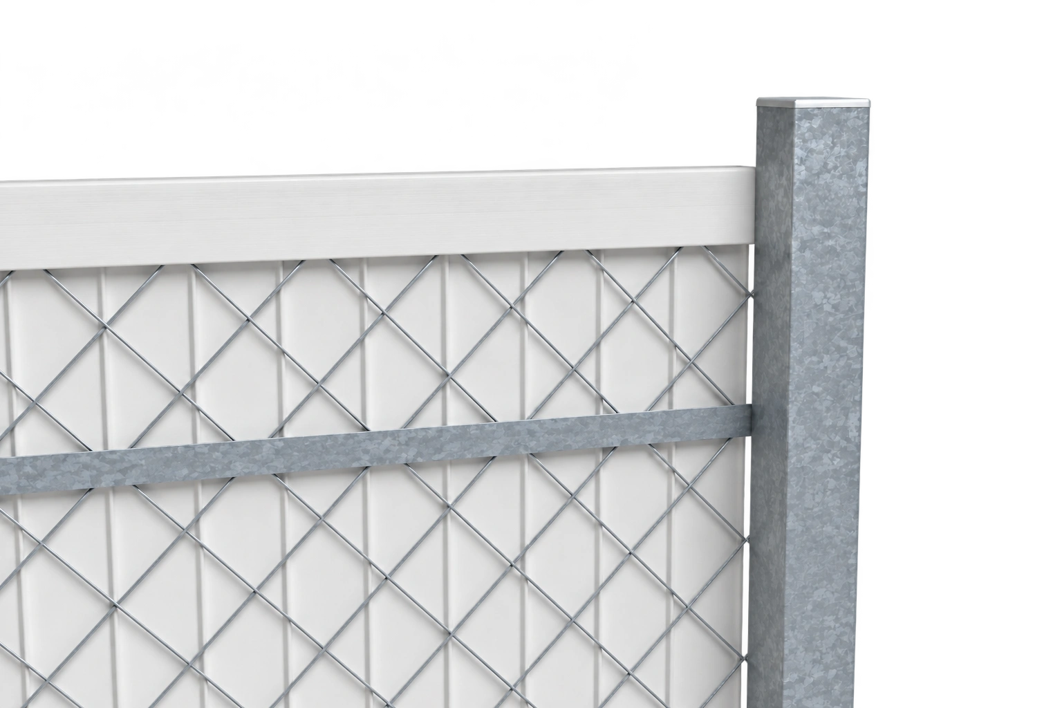
| Louvre profile | 55×8×3 mm, edges folded at 135° |
| Height | 1.50 m · 2.30 m |
|---|---|
| Post spacing | 2.00 m |
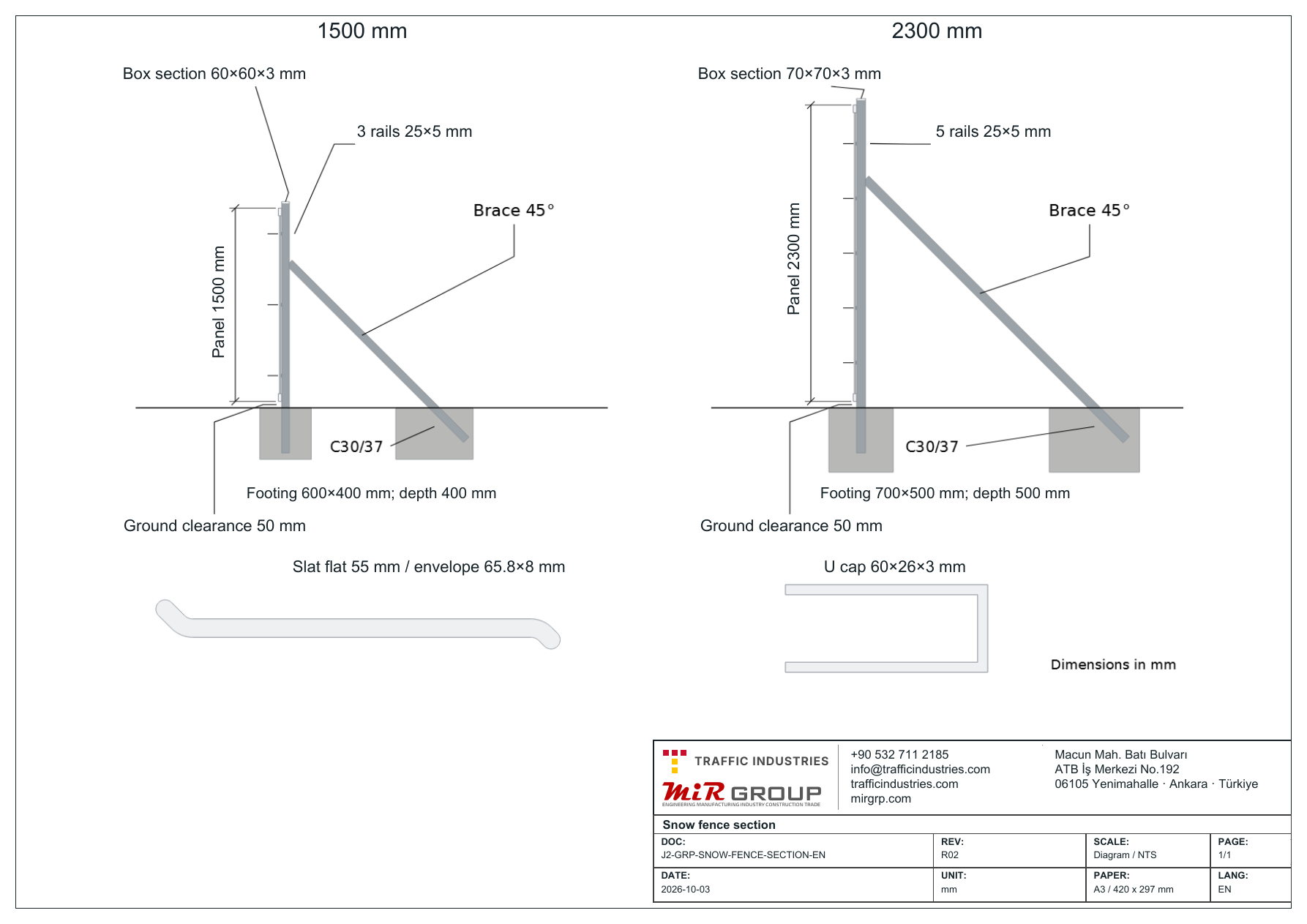
| Post section | Box section 60×60×3 mm (1.50 m) · 70×70×3 mm (2.30 m) |
| Rails | 3 rows (1.50 m) · 5 rows (2.30 m); 25×5 mm flat bar |
| Louvre profile | 55×8×3 mm, edges folded at 135° |
| Panel cap | U profile 60×26×3 mm, top and bottom |
| PVC reference (KTŞ 2013 Table 521-1) | For PVC fences: 1.50 m / 300 m snow-collection distance; 2.30 m / 1,500 m; wind ≤ 100 km/h. This is not a GRP site-capacity rating. |
| Foundation | 60×40 cm, 40 cm deep (1.50 m) · 70×50 cm, 50 cm deep (2.30 m) |
|---|---|
| Concrete | C30/37, reinforced |
| Brace | Same section as the post; one every 4 bays (1.50 m) or every 3 bays (2.30 m) |
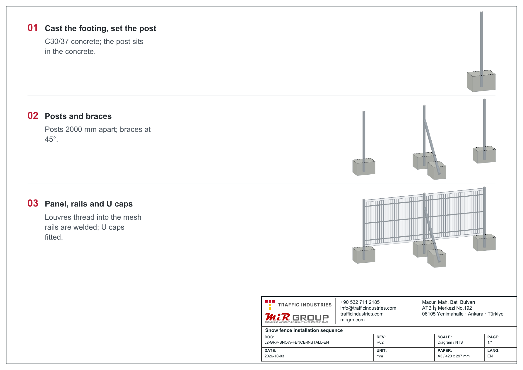
| Brace connection | Welded to the post at 45°; lower end 35–50 cm into the foundation concrete |
| Line ends | Two opposing braces |
| Panel | Vertical GRP louvres threaded into hot-dip galvanised, PVC-coated chain-link mesh, overlapping side by side |
|---|---|
| Colour | White |
| Caps | Panel: white GRP U profile, wall ≥ 3 mm · post top: white PVC |
| Cap fixing | ≥ 1.50 mm galvanised stainless tie wire |
| Steelwork coating requirement | The datasheet specifies 488 g/m² hot-dip galvanising with references to TS EN 10240 and TS EN ISO 1461, and TS EN 1179 for zinc; the product/batch report requires verification |
| Test | Standard | Value | Test condition |
|---|---|---|---|
| Yellowness index | ASTM E313 | ≤ 12 | 45°/0° geometry, 2° observer, spectrophotometer with D65 illuminant |
| Water absorption | EN ISO 62 | ≤ 0.4 % | 50×50 mm sample, 24 hours in water; from the mass difference |
| Chemical resistance | EN ISO 175 | No deposit or sediment is required | 7 days in 5 % sulphuric acid, 10 % hydrochloric acid, petrol and 10 % sodium chloride solution |
| Flame resistance | EN ISO 1066 | No ignition or self-extinguishing behaviour is required | One end of the sample is held in the flame; the distance at which burning stops is measured |
| Impact resistance | — | No crack of 6 mm diameter is required | Sample held at 30 °C; a 1000 g weight is dropped from 120 cm at 90° |
| Flexural strength | EN ISO 178 | ≥ 400 MPa | Three-point bending on a sample cut to the standard |
| Cold impact resistance | — | No crack of 6 mm diameter is required | Sample held at −30 °C for 2 hours; a 900 g weight is dropped from 150 cm at 90° |
Test requirements in the manufacturer’s datasheet; product/batch test documentation is verified for the quotation scope.
The files are free and download without registration.
Section 521 of the Highway Technical Specification (KTŞ 2013) is a dated reference; Table 521-1 covers PVC-coated snow fences on steel wire and does not verify the site capacity of the GRP product.
The applicable specification edition, fence position, height and distance from the road are determined for the project.
The KGM Snow and Ice Control Guide lists GRP fences on steel wire among open fence types in general; this is not an openness rating or performance certificate for KS-150.
The manufacturer’s datasheet specifies 488 g/m² galvanising for steelwork with reference to TS EN ISO 1461. This is not a measured coating result; method references do not prove product conformity.
Product/batch reports are verified for the quotation scope.
Height selection is determined in the design from the route’s wind and snow data and terrain. Standard heights are 1.50 and 2.30 m. The snow-collection distances and wind values in KTŞ 2013 Table 521-1 are references for PVC-coated fences; they are not verified site-capacity ratings for the GRP product. The applicable specification edition and project suitability are established for the quotation scope.
The line of a snow fence is set by the prevailing wind direction and the area where snow gathers. The aim is to stop wind-driven snow before it reaches the road. The distance from the road is set in the design from the site’s wind and snow data; when requesting a quotation, share the wind direction and snow accumulation along the route.
At 1.50 m the post is a 60×60×3 mm box section, the panel is tied with 3 rows of rails and one brace is used every 4 bays. At 2.30 m the post is 70×70×3 mm, the panel is tied with 5 rows of rails and there is a brace every 3 bays. The foundation grows with the height: 70×50 cm and 50 cm deep instead of 60×40 cm and 40 cm deep. Other heights are made to order.
In the design, each post sits on its own foundation, cast in reinforced ready-mixed C30/37 concrete. For the 1.50 m height the foundation is 60×40 cm on plan and 40 cm deep; for 2.30 m it is 70×50 cm and 50 cm deep. Braces share the posts’ foundations, with their lower ends 35–50 cm in the concrete. Suitability of these dimensions is verified in the installation design for the site’s ground, wind and snow conditions.
The manufacturer’s datasheet requires no crack of 6 mm diameter when a 900 g weight is dropped from 150 cm at 90° onto a sample held at −30 °C for 2 hours. No deposit or sediment after 7 days in 10 % sodium chloride, 5 % sulphuric acid, 10 % hydrochloric acid and petrol is also a datasheet requirement. Hot-dip galvanising at 488 g/m² is specified for steel posts, braces and rails. These requirements are not completed tests or coating measurements; product/batch reports are matched to the quotation scope and verified.
GRP traffic & road safety products — all modelsStandard cross-reference table40'HQ container calculationDescribe the job, we list the equipment
Quantity, destination country and your specification if you have one. A technical answer comes back the same day; pricing is prepared by a person, never auto-generated.