Get a quote for this product
Quantity, destination country and your specification if you have one. A technical answer comes back the same day; pricing is prepared by a person, never auto-generated.
Request a QuoteTell us quantity, country and mounting type — a technical answer comes back the same day.
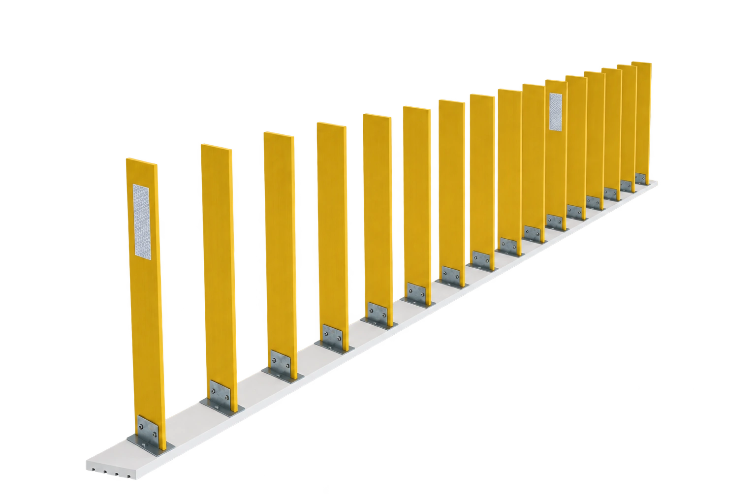
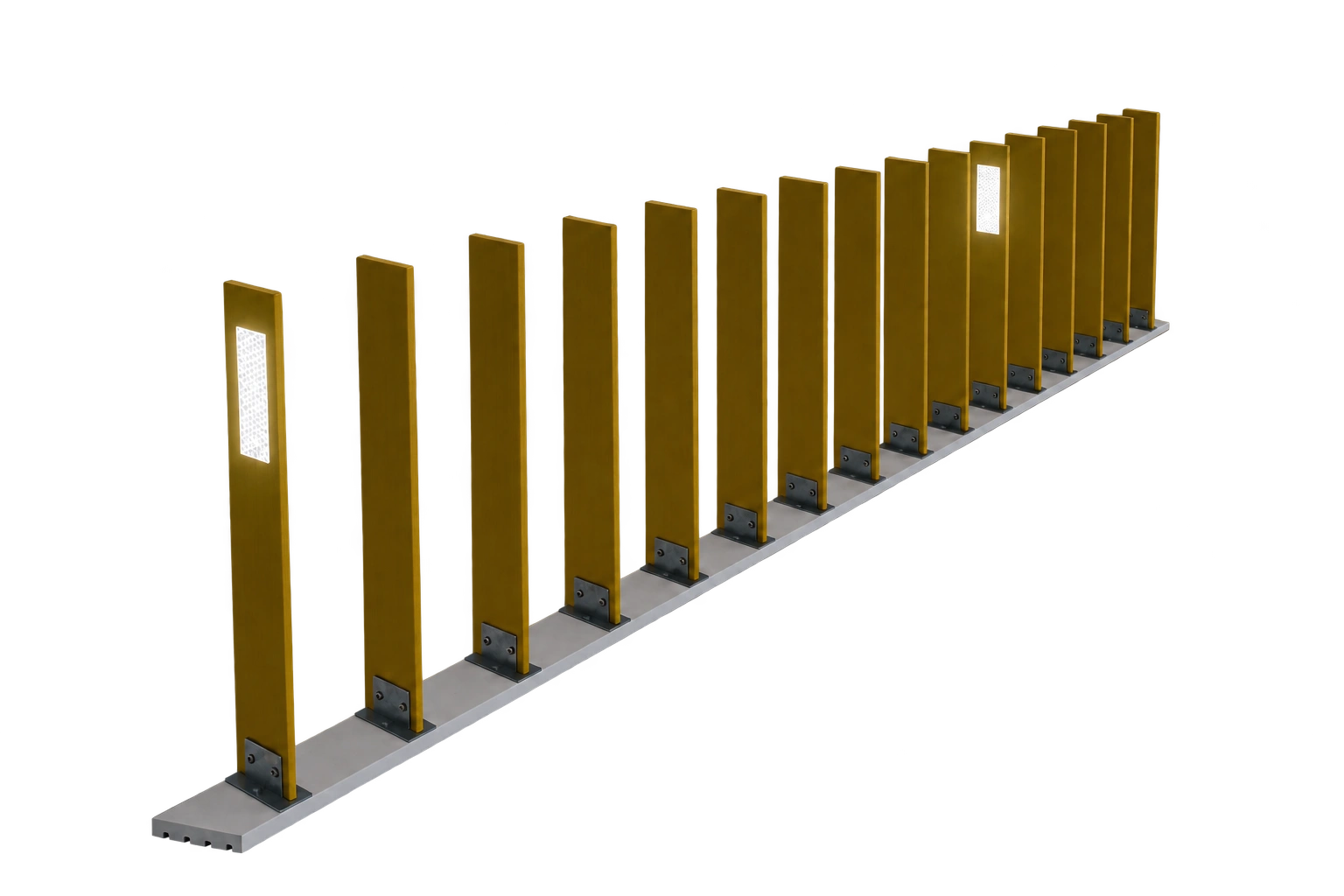
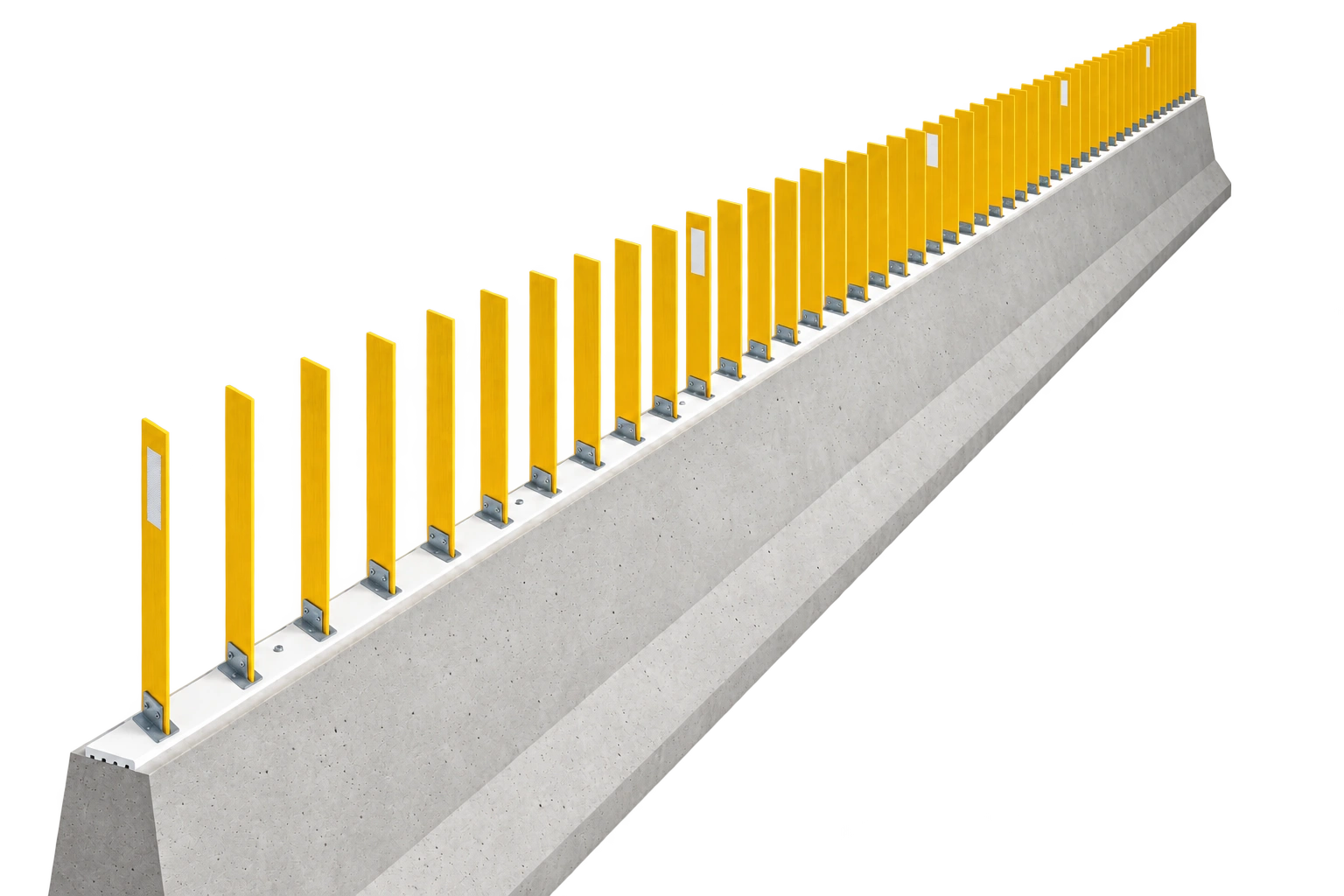
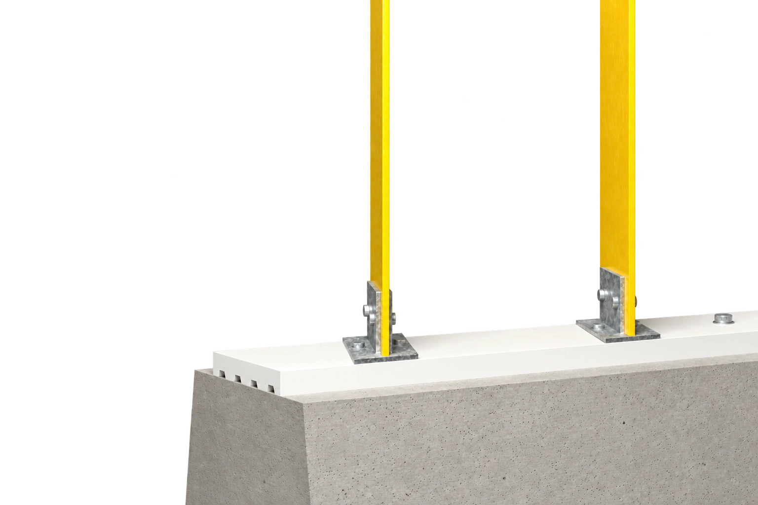
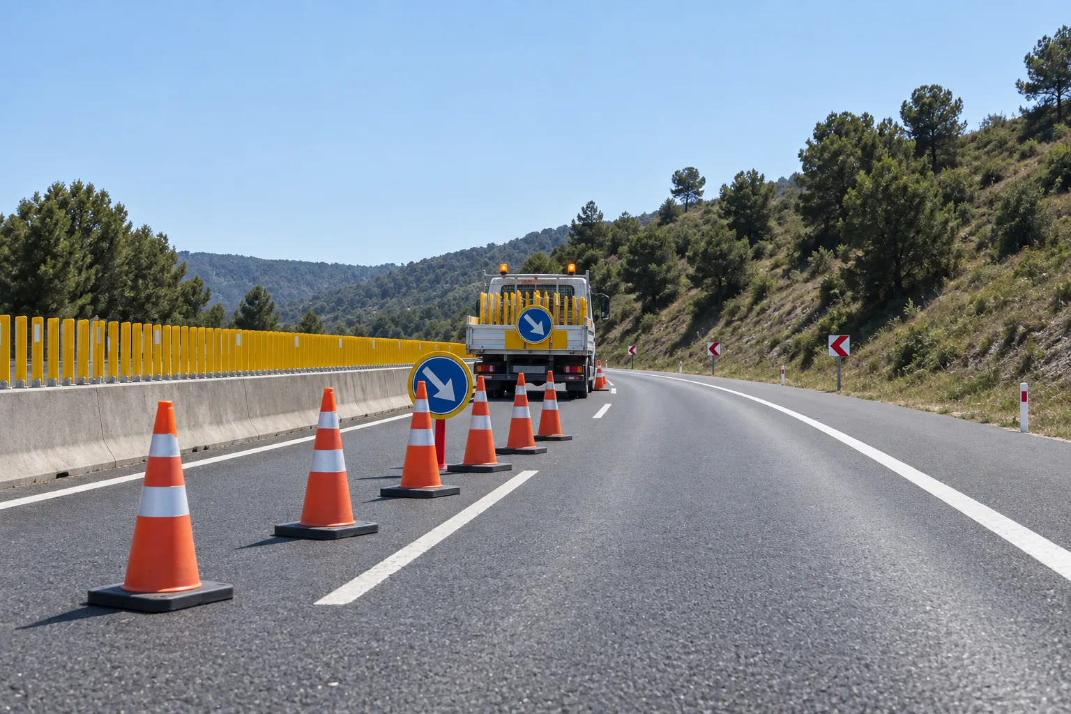
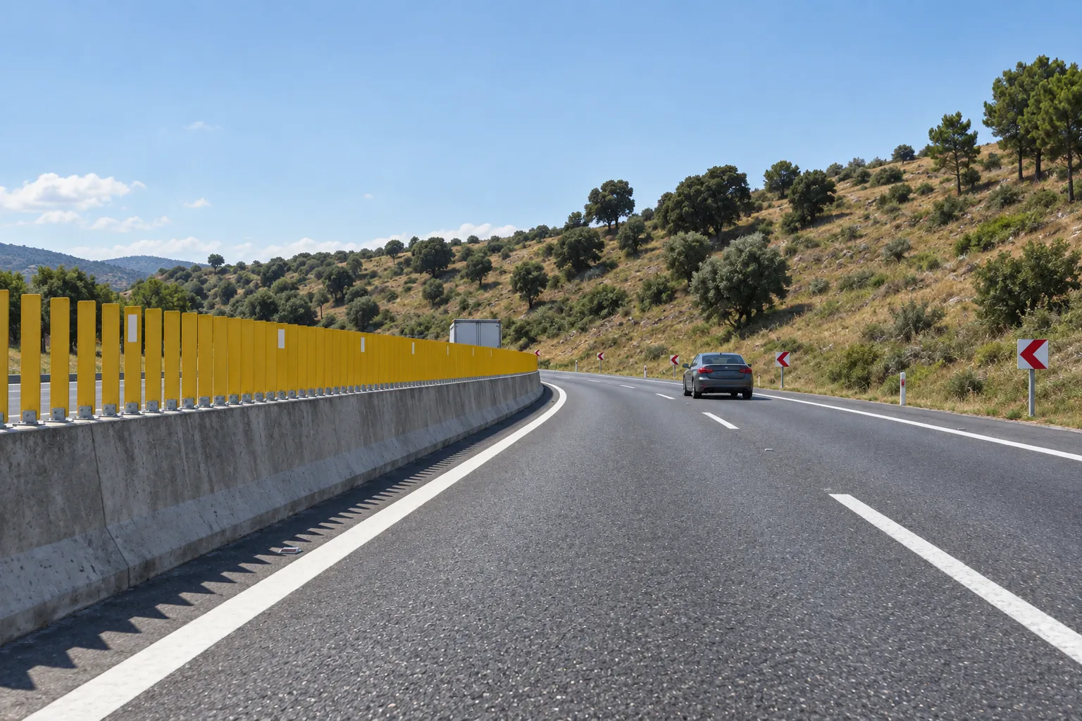
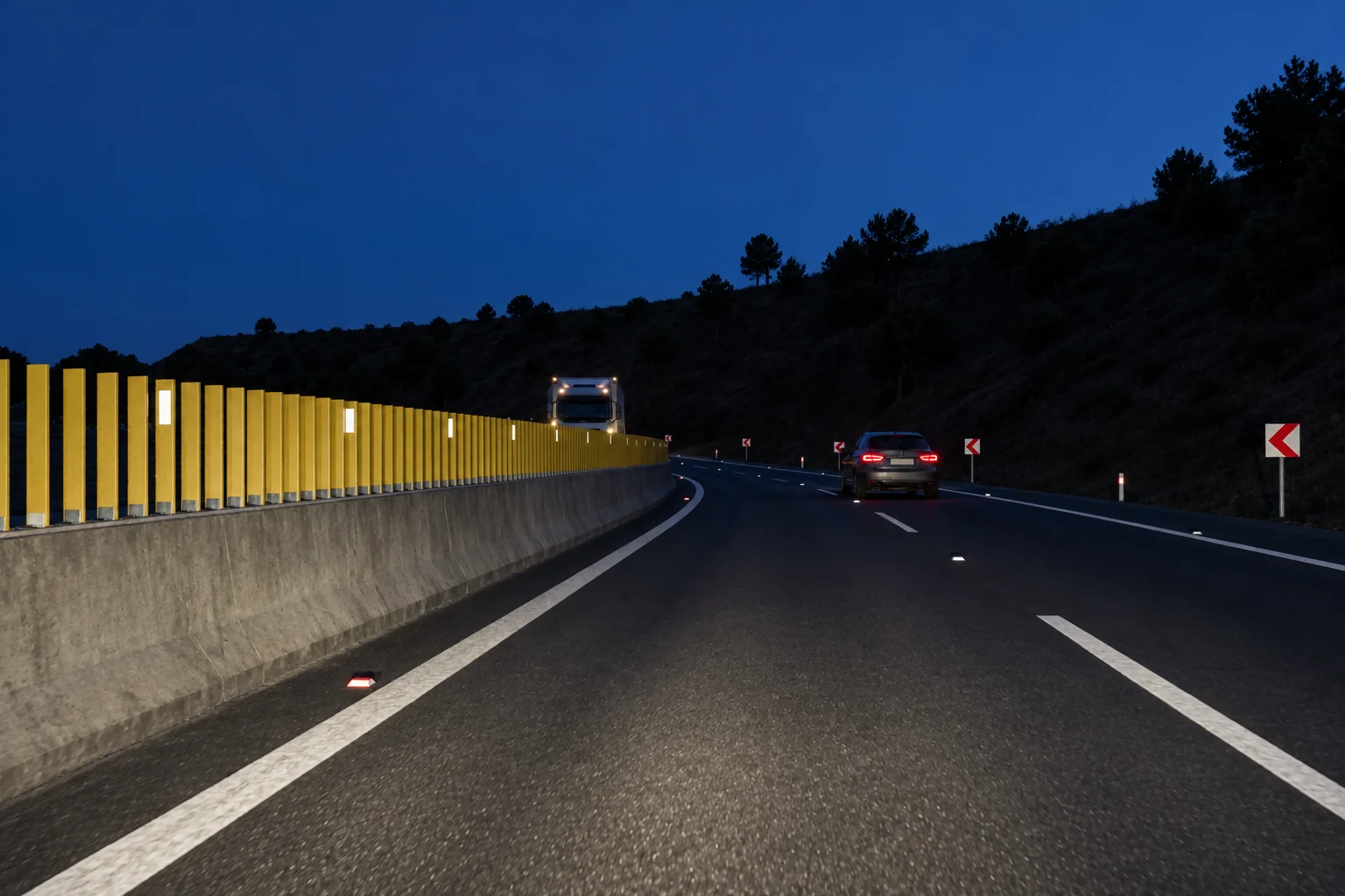
The modular GRP anti-glare screen is mounted on top of the concrete barrier on motorways and link roads to stop the headlights of oncoming traffic from affecting the driver. Vertical GRP blades set at an angle along a continuous GRP rail cut off the oncoming headlights. Light and modular, it is easy to install; the module length matches the precast barrier element.
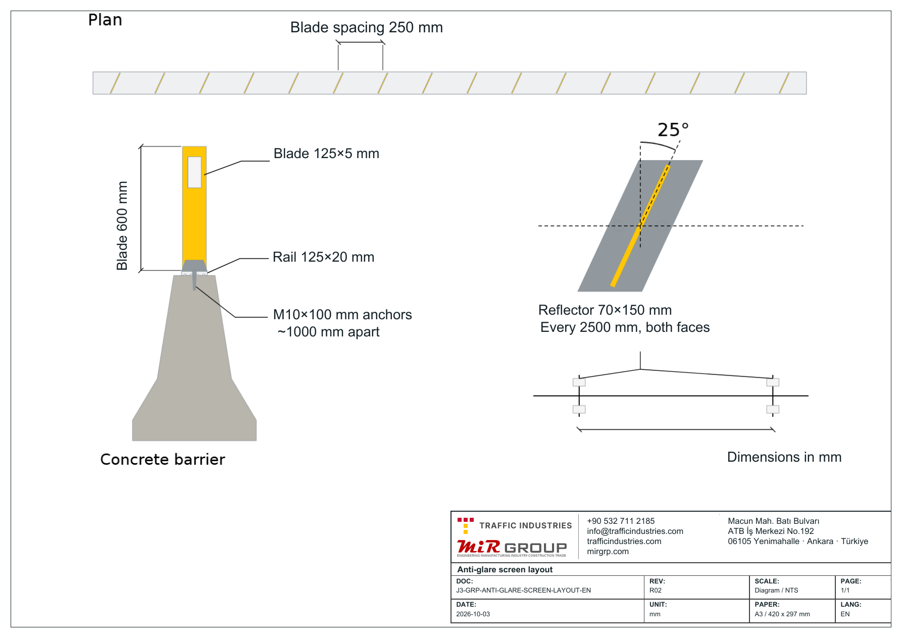
| Blade profile | 125 mm wide, 5 mm wall |
|---|---|
| Rail profile | 125 mm wide, 20 mm thick |
| Blade spacing | 250 mm (between fixings on the rail) |
| Blade height | At least 600 mm; planned against the barrier height |
|---|---|
| Blade profile | 125 mm wide, 5 mm wall |
| Rail profile | 125 mm wide, 20 mm thick |
| Blade spacing | 250 mm (between fixings on the rail) |
| Blade angle | 25° from the transverse axis; 65° from the rail direction |
| Module length | The precast barrier element length; any length on cast-in-place barrier |
| Base | Top of the concrete barrier, levelled before mounting |
|---|---|
| Rail fixing | M10×100 mm steel expansion anchors, about 1 m apart |
| Fixings | All metal parts galvanised |
| Rail | GRP, white |
|---|---|
| Blade | GRP, yellow |
| Reflector | 70×150 mm, every 2.5 m, on both faces of the blade |
| Test | Standard | Value | Test condition |
|---|---|---|---|
| Heat deflection temperature | TS 1400 | ≥ 100 °C | Conditioned 24 hours at 23 ± 2 °C and 50 ± 5 % relative humidity before testing |
| Water absorption | TS 702 | ≤ 0.40 % | Conditioned sample |
| Chemical resistance | TS 710 | No change in appearance or structure is required | The datasheet requires no colour change or sediment in the test solution |
| Flame resistance | TS 1066 | No ignition or self-extinguishing behaviour is required | Conditioned sample |
| Impact resistance | TS 10381 | No damage within a 5 mm diameter area is required; deflection must be ≤ 2 mm | Measured after the impact test |
| Wind resistance | TS 10381 | ≤ 2.5 % | Transient deformation 10 minutes after the test, as a share of the support span |
| Barcol hardness | TS 10381 | ≥ 40 Barcol; change ≤ 30 % | Hardness change on the conditioned sample |
| Flexural strength | TS 985 | ≥ 150 MPa (1500 kgf/cm²) | Conditioned sample |
| UV resistance | ASTM G53 | No visible colour change is required | 500 hours |
| Thermal cycling | TS 10381 | Standard requirement specified in the datasheet | Conditioned sample |
| Reflective material — water | — | No blistering or lifting is required | Bonded to the profile, 48 hours in water |
| Reflective material — adhesion | — | The piece must not peel off | 2×2 cm cross-cut on the profile, the piece is pulled |
| Reflective material — salt spray | ISO 3768 | Salt-spray test conditions listed in the datasheet; verify the product report | 22 hours; 5 % sodium chloride solution at 35 °C; 2 samples |
Test conditions and acceptance requirements listed in the manufacturer’s datasheet; these are not product/batch test-result reports.
The files are free and download without registration.
EN 12676-1 covers optical effectiveness and mechanical characteristics of road anti-glare systems; EN 12676-2 covers test methods. These references are not conformity certificates for AG-600; product-matched reports for optical effectiveness, wind resistance and ageing require verification.
ISO 39001 covers organizational road traffic safety management systems and cannot serve as a product test certificate.
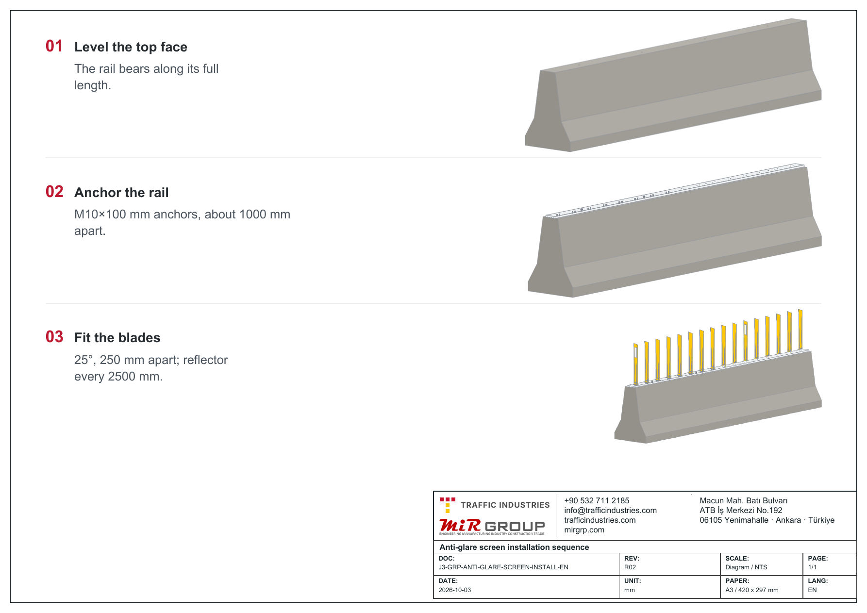
An anti-glare screen is installed on motorways and link roads on top of the concrete barrier that separates the two directions. Its purpose is to stop the headlights of oncoming traffic from affecting the driver. The top of the barrier is levelled before mounting and the rail is anchored to the concrete with M10×100 mm steel expansion anchors about 1 m apart.
On precast concrete barrier the module length equals one barrier element. On cast-in-place barrier any length can be made; it is chosen so that one impact does not damage the whole system. When requesting a quotation, state the barrier type and its element length.
The blade height is at least 600 mm and is planned against the height of the barrier it sits on. The blade is 125 mm wide with a 5 mm wall; blades are set at 25° from the transverse axis (65° from the rail direction), 250 mm apart.
Every 2.5 m a 70×150 mm reflective sheet is bonded to both faces of a blade, so the line reads from both directions. The manufacturer’s datasheet requires no blistering or lifting after 48 hours in water and no peeling in a 2×2 cm cross-cut test. For salt spray, it lists test conditions of 22 hours, 2 samples, 5 % sodium chloride solution and 35 °C; that row does not state an acceptance result. Product/batch test-result reports are verified for the quotation scope.
GRP traffic & road safety products — all modelsStandard cross-reference table40'HQ container calculationDescribe the job, we list the equipment
Quantity, destination country and your specification if you have one. A technical answer comes back the same day; pricing is prepared by a person, never auto-generated.