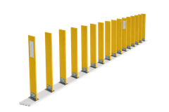
What does a GRP anti-glare screen do?
A practical guide to site fit, sightlines and project checks.
What the screen does
A modular GRP anti-glare screen uses upright blades on a supporting rail to limit the driver's direct view of opposing headlamps across the median. It can also help make the median edge easier to identify at night. Its effect depends on the road geometry, blade arrangement and viewing position, so the layout must be checked for the actual site.
Where it may be appropriate
Divided-highway medians are a typical application; screens can be considered for temporary or permanent layouts. Start with the glare observed on the route. Identify the affected direction, the time it occurs and how lighting, curves or changes in level affect the view. A suitable layout addresses that problem while preserving the views drivers need to read signs and follow traffic.
Check sightlines and geometry
Review both approaches, including curves, ramps, changing grades, merges, junctions and the barrier's position. Compare driver eye and headlamp positions with the proposed screen. A view that works at one point may change along a curve or at a different vehicle height. The design team should select blade height, angle and spacing for the required sightline and verify that signs, merge areas and other essential views remain clear.
Check the carrier and connection
The screen manages glare and guides vision; it is not a vehicle-restraint barrier. Confirm that adding it will not impair the carrier’s intended safety function. Use a concrete or steel carrier only when the screen, rail, fixings and carrier have been assessed together for the project. The design review needs the carrier condition, substrate, connection detail, module joints and installation access. Wind actions and the capacity of the barrier and fixings require project-specific confirmation; do not infer them from a product name.
Specify evidence and maintenance
Give the supplier the road location and authority, alignment drawings, observed glare condition, affected directions and carrier details. Identify the sightlines that must stay open, the design wind input and access limits. Request product-matched evidence for optical effectiveness, wind resistance and ageing, plus installation and inspection instructions. Agree acceptance criteria with the project team. Before installation, plan safe access to inspect blades, rail, joints and fixings, and a way to replace damaged parts without compromising the carrier.
Sources
General material and practice information comes from these sources; for product-specific values, refer to the documents for the model offered.